What Is an Oxygen Sensor(O2 Sensor)? What It Does and How It Works
An O2 sensor measures oxygen remaining in a vehicle’s exhaust and sends that information to the engine control unit, or ECU, so fuel delivery can be adjusted and emissions can be monitored. The oxygen sensor is one of the main feedback devices that lets a modern engine correct a rich or lean mixture after combustion has occurred. Depending on its position and design, it can help control the air fuel ratio, check catalytic converter performance, or do both. A failing sensor can therefore affect fuel economy, drivability, emissions, and diagnostic trouble codes, although proper testing is important before replacing one.

James Mitchell
Senior Automotive Writer
12+ years writing clear, practical guides on vehicle maintenance and emissions systems.
What an O2 Sensor Does in the Engine Management System
The primary job of an O2 sensor is to report how much oxygen remains in the exhaust stream after combustion. The ECU compares that feedback with other information, including engine load, throttle position, intake airflow, coolant temperature, and operating conditions. It then makes small fuel corrections so combustion stays within the range the engine and emissions system are designed to use. This closed loop control happens continuously once the sensor reaches its operating condition and the ECU has entered closed loop operation.
How the ECU Uses Oxygen Feedback
When the exhaust indicates a lean condition, there is relatively more oxygen left after combustion. When it indicates a rich condition, there is relatively less oxygen. A conventional switching oxygen sensor changes its signal sharply as the mixture crosses the stoichiometric point. The ECU uses those changes as feedback and adjusts injector pulse width in small steps. A wideband sensor provides more detailed information across a broader mixture range, allowing finer control during conditions where a simple rich or lean indication is not enough.
Why Lambda Matters to Combustion and Emissions
Lambda is a way of describing the relationship between the actual air fuel mixture and the stoichiometric mixture. For gasoline, lambda 1 corresponds approximately to 14.7 parts air to 1 part fuel by mass. Around this point, a three way catalytic converter can efficiently process major regulated pollutants when the rest of the engine and emissions system are working correctly. That is why the term lambda sensor is commonly used outside North America for the same general component most drivers call an oxygen sensor or O2 sensor.
How an Oxygen Sensor Works Inside the Exhaust Stream
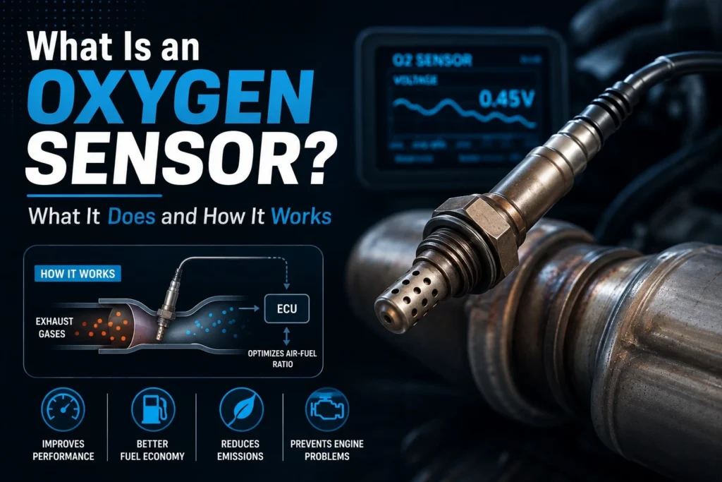
An oxygen sensor is threaded into the exhaust where its sensing element is exposed to hot exhaust gas while its wiring connects to the vehicle electrical system. Different designs produce different electrical signals, but they all convert information about residual oxygen into a signal the ECU can interpret. Modern sensors also commonly include an internal heater so the sensing element reaches a useful operating temperature quickly after startup, instead of depending only on exhaust heat.
Zirconia Switching Sensors
A traditional zirconia oxygen sensor uses a ceramic sensing element that responds to the difference in oxygen concentration across the element. Near stoichiometric combustion, the output changes rapidly between a lower voltage in lean exhaust and a higher voltage in rich exhaust. A healthy warmed switching sensor can move roughly between about 0.1 volt and 0.9 volt as mixture conditions change. That switching behavior is why scan data or an oscilloscope can be useful when checking sensor activity on an application that uses this design.
Wideband Air Fuel Ratio Sensors
A wideband oxygen sensor, often called an air fuel ratio sensor, can report mixture information over a much broader range than a conventional switching sensor. Its internal construction uses a measurement cell and an oxygen pump cell so the control module can determine how far the mixture is from the target, not merely whether it is on the rich or lean side. Because the signal strategy is different, a wideband unit should not be judged by the same simple voltage expectations used for a conventional zirconia switching sensor.
What the Heater Circuit Does
A heated oxygen sensor contains an electrical heating element that brings the sensing element to operating temperature quickly. Faster warmup allows feedback control and emissions monitoring to begin sooner after a cold start. Heater circuits are monitored on many vehicles, so an open heater, damaged wiring, poor ground, blown fuse, or power supply problem can set a diagnostic trouble code even when the sensing element itself has not completely failed. Testing the heater circuit separately can prevent an unnecessary sensor replacement.
| Sensor or role | How it reports exhaust oxygen | Common position | Main purpose |
|---|---|---|---|
| Zirconia switching sensor | Changes rapidly between lean and rich voltage states | Before or after the converter | Fuel control or catalyst monitoring, depending on application |
| Wideband air fuel ratio sensor | Provides a broader, more precise mixture signal | Often before the converter | Precise mixture control across a wider operating range |
| Titanium sensor | Changes electrical resistance with exhaust oxygen conditions | Varies by older application | Fuel control or monitoring on specific systems |
| Heated oxygen sensor | Uses an internal heater in addition to its sensing circuit | Common in modern exhaust systems | Reaches operating temperature more quickly after startup |
| Upstream sensor | Reads exhaust before catalytic conversion | Before the converter | Primary feedback for mixture control on many vehicles |
| Downstream sensor | Reads exhaust after catalytic conversion | After the converter | Helps the ECU monitor converter performance on many vehicles |
Where Oxygen Sensors Are Located and Why Position Changes Their Job
Sensor position matters because exhaust gas contains different information before and after the catalytic converter. A vehicle can have one exhaust bank or multiple banks, and it can have more than one converter. That is why scan tools and service information identify sensor location by bank and sensor number rather than by appearance alone. On many gasoline vehicles, Sensor 1 is upstream of the converter and Sensor 2 is downstream, but the exact layout must be confirmed for the engine being serviced.
Upstream Sensor: Fuel Control Comes First
The upstream oxygen sensor is mounted before the catalytic converter, where it sees exhaust directly from the engine. On many systems, this sensor provides the feedback the ECU uses to correct fuel delivery. A search result or parts listing may describe the same position as O2 sensor upstream. When an upstream sensor becomes slow, biased, contaminated, or electrically faulty, fuel trim can move away from normal as the ECU reacts to inaccurate information. Exhaust leaks ahead of the sensor can also introduce oxygen and make the signal misleading.
Downstream Sensor: Catalyst Monitoring Is the Main Role
A downstream oxygen sensor is located after the catalytic converter. Its main job on many OBD II vehicles is to help the ECU judge how effectively the converter is storing and processing oxygen as exhaust passes through it. A healthy converter tends to smooth the downstream pattern compared with the active switching seen ahead of the converter. If upstream and downstream behavior becomes too similar under the conditions used by the monitor, the ECU may set a catalyst efficiency code, although leaks, sensor faults, and engine problems must also be considered.
The exact difference between the two positions deserves its own diagnosis focused explanation because bank numbering, sensor numbering, and scan patterns vary by vehicle.
Symptoms of a Bad O2 Sensor and Similar Problems
A failing O2 sensor does not produce one unique symptom. Some failures trigger a check engine light with little noticeable change in drivability, while others can contribute to poor fuel economy, rough running, hesitation, elevated emissions, or an incorrect fuel mixture. The key is to treat the sensor signal as evidence, not as proof that the sensor is the root cause. Vacuum leaks, exhaust leaks, misfires, injector problems, fuel pressure faults, wiring damage, and converter problems can all influence oxygen readings.
Common Warning Signs
Typical warning signs include a check engine light, increased fuel consumption, unstable idle, reduced response, failed emissions testing, or trouble codes related to sensor activity, heater circuits, mixture control, or catalyst efficiency. An upstream sensor that responds slowly can interfere with fuel correction. A downstream sensor problem may be more likely to affect emissions monitoring than day to day drivability. Because vehicle strategies differ, the code description and live data should be checked before deciding which symptom belongs to which component.
| Symptom or finding | What it may suggest | What should be checked before replacement |
|---|---|---|
| Check engine light with oxygen sensor code | Sensor circuit, heater, response, or mixture issue | Connector condition, wiring, power, ground, exhaust leaks, and code specific tests |
| Poor fuel economy | Incorrect mixture feedback or another fuel control problem | Fuel trims, intake leaks, injector operation, air metering, and upstream sensor response |
| Rough idle or hesitation | Mixture problem, misfire, or biased sensor feedback | Misfire data, vacuum leaks, ignition condition, fuel delivery, and sensor data |
| Catalyst efficiency code | Converter performance concern or misleading oxygen data | Exhaust leaks, upstream and downstream patterns, mixture faults, and sensor response |
| Failed emissions test | Excess emissions or incomplete monitor readiness | Stored codes, readiness monitors, fuel control, converter operation, and leaks |
| Heater circuit code | Open heater, power supply issue, ground fault, or wiring damage | Fuse, heater resistance where specified, connector pins, and circuit voltage |
A Shop Example That Shows Why Testing Matters
I once checked a sedan that arrived after its owner had already bought an oxygen sensor because the scan tool showed a lean code. The upstream signal looked lean at idle, but the sensor reacted immediately when the throttle was opened. A smoke test found a split intake hose downstream of the airflow meter. That leak was feeding the engine unmetered air, so the sensor was accurately reporting a lean condition rather than causing it. Replacing the hose corrected the fuel trims and the warning light stayed off. The lesson was simple: a sensor can report a problem perfectly even when the sensor itself is healthy.
Why Sensors Fail or Become Contaminated
Oxygen sensors live in a harsh environment of heat, vibration, moisture, exhaust deposits, and repeated thermal cycles. Age can slow response, while oil ash, coolant contamination, excessive carbon, some silicone compounds, and inappropriate additives can damage or coat the sensing element. Wiring can melt against the exhaust, connectors can corrode, and threads can seize in the exhaust bung. If contamination is visible, the underlying engine problem should be corrected before fitting a new sensor or the replacement may be damaged again.
How to Diagnose an Oxygen Sensor Before Replacing It
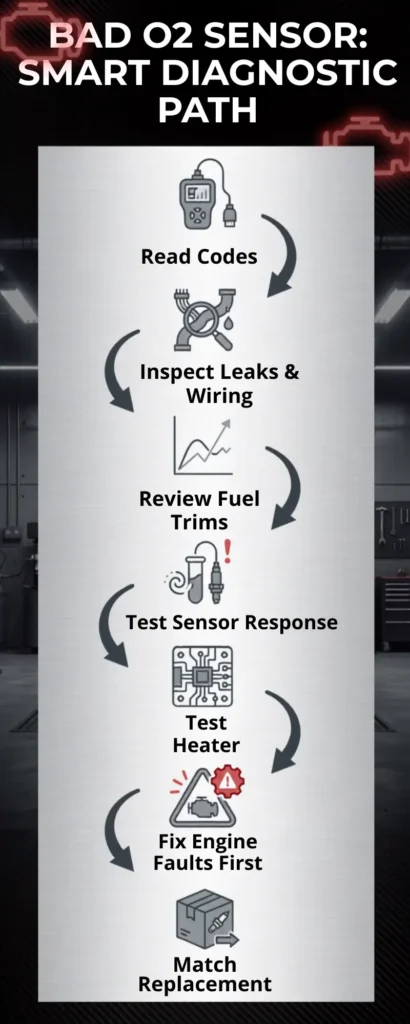
A good diagnosis starts with the exact trouble code and the vehicle service information. A code that mentions an oxygen sensor does not automatically mean the sensor itself is defective. The ECU can only judge the circuit and signal behavior it sees. Confirming power, ground, wiring integrity, exhaust condition, fuel control, and sensor response prevents the common mistake of replacing a part that was accurately reporting another fault.
Read Codes, Freeze Frame Data, and Fuel Trims
Begin with an OBD II scan tool and record stored codes, pending codes, freeze frame data, and readiness monitor status before clearing anything. Look at short term and long term fuel trims, upstream sensor response, downstream sensor behavior, engine temperature, and load. On a conventional switching sensor, the upstream pattern should respond as mixture changes once the system is warm. On a wideband system, use the manufacturer specified parameter and test method rather than expecting the same voltage pattern as a narrow switching sensor.
Check the Circuit and Create a Controlled Response
Inspect the harness where it passes near the exhaust and verify the connector is fully seated. If a heater code is present, check the heater power, ground control, and resistance according to service information. When appropriate, a technician can create a controlled rich or lean change and watch whether the sensor responds promptly. An oscilloscope shows switching behavior clearly on many conventional sensors, while a multimeter can be useful for certain circuit tests. Test methods vary, so pin assignments and expected values must come from the correct service information.
| Diagnostic step | What you are trying to learn | A result that changes the next step |
|---|---|---|
| Confirm the exact code | Whether the fault concerns signal, heater, mixture, or catalyst monitoring | A circuit code sends diagnosis toward wiring and electrical checks first |
| Inspect exhaust and wiring | Whether outside air or electrical damage is distorting the signal | A leak or melted harness must be repaired before judging the sensor |
| Review fuel trims | Whether the ECU is adding or subtracting unusual fuel | Large trim corrections point toward mixture diagnosis, not automatic sensor replacement |
| Compare live sensor data | Whether the signal is active, plausible, and appropriate for position | A fixed or implausible value requires circuit and response testing |
| Command or create mixture change | Whether the sensor reacts to a known rich or lean condition | A quick response suggests the sensor may be reporting correctly |
| Test heater circuit | Whether the internal heater and its supply circuit are intact | Open resistance or missing power requires electrical repair or sensor replacement as applicable |
A complete test procedure for scan patterns, heater resistance, and controlled mixture changes is better handled separately because the correct values depend on sensor design and vehicle circuitry.
Replacement Cost and Installation Considerations
For many common vehicles, replacing one oxygen sensor may cost roughly $150 to $500 including parts and labor, while difficult access, premium wideband sensors, seized threads, or luxury applications can push the total higher. Before ordering parts, match the sensor by year, make, model, engine, exhaust bank, and position. A direct fit connector usually reduces installation risk. Never splice a sensor simply because the wire colors look similar unless the replacement manufacturer provides a vehicle specific procedure.
Choosing the Correct O2 Sensor for Your Vehicle
Oxygen sensors may look similar while using different sensing elements, heater resistance, connectors, calibration, and wiring. The safest parts lookup uses the vehicle identification number when available, then confirms engine, emissions specification, bank, and sensor position. A universal sensor can be appropriate when it is specifically cataloged for the application and installed according to the manufacturer instructions, but a direct fit sensor is usually easier for a do it yourself repair because the correct connector is already attached.
Vehicle Specific Fit Matters More Than Appearance
When shopping for a Nissan oxygen sensor, or for a sensor on any other brand, do not order by thread size and connector shape alone. Some vehicles use an air fuel ratio sensor in the front position and a conventional heated sensor behind the converter. Others use wideband technology in more than one position. Catalog terminology can also vary between manufacturers. Confirm the exact engine and sensor location before buying, and compare the original equipment number when a reliable catalog provides it.
Why One Part Can Have Several Names
The same general component is described by several names across markets and catalogs. Oxygen sensor and lambda sensor are the most common. Spanish catalogs may use sensor de oxígeno, while listings without accent marks may show sensor de oxigeno or the plural sensores de oxigeno. Search engines also surface 02 sensors, with a zero instead of the letter O. These terms usually describe the same family of exhaust oxygen sensing parts, not separate technologies by themselves.
Online listings can also contain clumsy phrases such as o2 sensor sensor, oxygen sensor oxygen sensor, lambda sensor o2 sensor, oxygen o2 sensor, o2 oxygen sensor, lambda sensor auto, automotive o2 sensor, auto oxygen sensor, and car o2 sensor. Those phrases are usually catalog or search wording. The correct replacement still depends on sensor technology, connector, heater specification, vehicle application, and exact exhaust position.
Maintenance and Realistic Replacement Expectations
There is no single replacement interval that applies to every oxygen sensor on every vehicle. Service life depends on sensor design, engine condition, fuel and oil consumption, contamination, heat exposure, and the manufacturer maintenance strategy. Some parts manufacturers publish application specific replacement recommendations, while many vehicle makers rely on onboard diagnostics and service procedures rather than routine replacement at one universal mileage. If the engine burns oil or coolant, repair that condition before installing new oxygen sensors whenever possible.
James Mitchell
Senior Automotive Writer
12+ years writing clear, practical guides on vehicle maintenance and emissions systems.
Frequently Asked Questions
Conclusion:
An O2 sensor is a feedback and monitoring device, so the best repair decision comes from understanding what its signal is telling the ECU. If a code points toward an oxygen sensor, confirm the location, sensor type, wiring, exhaust condition, and live response before buying a replacement. When testing shows the sensor is truly slow, biased, electrically open, or otherwise faulty, install the correct application specific part and correct any contamination source at the same time.