
How Does a Catalytic Converter Work?
Most drivers know they have a catalytic converter somewhere under their car. Far fewer understand what it actually does, how it works, and why the chemistry inside that canister-shaped component is genuinely remarkable. After spending years working hands-on with exhaust systems, I can tell you that the catalytic converter is one of the most elegantly engineered parts on any modern vehicle. This guide takes you through every layer of how it operates, from the raw chemistry to the electronic feedback systems that keep it running at peak efficiency.

James Mitchell
Senior Automotive Writer
12+ years writing clear, practical guides on vehicle maintenance and emissions systems.
What Does a Catalytic Converter Do in a Car?
A catalytic converter works by converting toxic exhaust gases produced by an internal combustion engine into significantly less harmful substances before they exit the tailpipe. Hot exhaust gases pass through a precious metal-coated honeycomb substrate inside the converter, triggering chemical reactions that transform carbon monoxide, unburned hydrocarbons, and nitrogen oxides into carbon dioxide, water vapor, and nitrogen gas.
That is the short answer. The rest of this article explains exactly how that transformation happens at a chemical level, how the engine management system keeps the converter working efficiently, and what goes on inside this component every single second your engine is running
How the Catalytic Converter Came to Exist?
To fully appreciate how a catalytic converter works, it helps to know why it was invented in the first place. By the early 1950s, research linking Los Angeles smog to vehicle exhaust was already alarming scientists. French mechanical engineer Eugene Houdry, an expert in catalytic oil refining, became deeply concerned about the role of exhaust gases in urban air pollution. He founded a company called Oxy-Catalyst and began developing converter technology initially for industrial smokestacks and warehouse forklifts.
His work eventually led to a United States patent for an automotive catalytic converter, laying the technical foundation for what would become a mandatory component on every passenger vehicle. In 1975, the United States Environmental Protection Agency introduced strict new emissions regulations, and automakers responded by fitting two-way catalytic converters to virtually all new petrol-powered vehicles. Those early two-way units only handled carbon monoxide and hydrocarbons.
The three-way catalytic converter, which also tackles nitrogen oxides, was first commercialized by Volvo in 1977 on California-specification vehicles. By 1981, tightening federal NOx regulations pushed nearly every automaker to adopt the three-way design paired with electronic engine management. That three-way system is what most petrol vehicles still use today, refined and improved but chemically identical in principle to what Houdry pioneered decades earlier.
Catalytic Converter Anatomy: Components Explained
Understanding how a catalytic converter works begins with understanding what it is made of. This is not a simple metal box. It is a precisely engineered assembly of six distinct components, each serving a specific purpose in making the conversion process possible.
The Stainless Steel Outer Shell
The outer casing is constructed from ribbed stainless steel, chosen specifically for its ability to withstand continuous exposure to extreme heat, exhaust vibration, and road debris. The ribbed design is not cosmetic. It minimizes thermal expansion and distortion as the converter cycles through heating and cooling thousands of times over its lifespan. The ribbed pockets also protect the internal cushioning mat from direct contact with exhaust gases, extending the service life of the entire assembly.
The Ceramic or Metallic Honeycomb Substrate
Inside the shell sits the substrate, the structural backbone of the entire converter. In the vast majority of passenger vehicles, this is a cordierite ceramic monolith with a honeycomb channel structure. The cordierite ceramic formulation used in modern converters was invented by Rodney Bagley, Irwin Lachman, and Ronald Lewis at Corning Glass, work significant enough to earn them induction into the National Inventors Hall of Fame in 2002.
The channels in the substrate run parallel and are typically square in cross-section rather than hexagonal, which optimizes gas flow and structural integrity under thermal stress. In applications requiring exceptionally high heat resistance, such as racing or heavy-duty commercial vehicles, metallic foil substrates made from FeCrAl alloys are used instead.
The geometry of the substrate solves a fundamental engineering challenge: how do you maximize the surface area available for chemical reactions while minimizing the total volume and weight of the component? A single automotive substrate can contain hundreds of tiny channels per square inch, providing a combined reactive surface area of several square meters inside a component no larger than a shoebox.
The Washcoat Layer
Coating every channel wall of the substrate is a thin, porous layer called the washcoat. This is perhaps the least-discussed component in most articles about how a catalytic converter works, yet it is absolutely critical to the converter’s effectiveness.
The washcoat is composed of aluminum oxide combined with other metal oxides including titanium dioxide and silicon dioxide. Its surface is intentionally rough and irregular at a microscopic level, which multiplies the effective surface area of the substrate enormously beyond what the channel geometry alone provides. Embedded within the washcoat are cerium oxide and ceria-zirconia compounds, which serve as oxygen storage promoters. This oxygen storage function plays a crucial role in maintaining conversion efficiency across varying engine operating conditions, something we will cover in detail shortly.
Platinum, Palladium, and Rhodium: Roles in Catalytic Converters
The precious metal catalysts are deposited onto the washcoat in precise concentrations. Each of the three platinum group metals performs a distinct chemical function, and they cannot simply be substituted for one another.
Rhodium is the primary reduction catalyst. It is almost uniquely effective at breaking apart nitrogen oxide molecules, stripping the oxygen away from the nitrogen and allowing the nitrogen atoms to recombine as harmless nitrogen gas. Palladium functions primarily as an oxidation catalyst, promoting the combination of carbon monoxide and hydrocarbons with oxygen. Platinum performs both reduction and oxidation duties, making it the most versatile of the three.
Roughly 60% of global platinum group metal production goes into catalytic converters, which tells you everything you need to know about how dependent modern emissions control is on these rare materials.
The Catalyst Cushioning Mat
Wrapped around the substrate and positioned between it and the outer shell is an intumescent cushioning mat. This mat does two things simultaneously. It cushions the brittle ceramic substrate against vibration and road shock, preventing cracks from forming in the honeycomb structure. It also accommodates the significant thermal expansion that occurs as the converter heats from ambient temperature to operating temperature during every drive cycle. Without this mat, the ceramic core would fracture under the mechanical stress of normal use within a relatively short time.
Upstream and Downstream Oxygen Sensor Ports
Built into the converter housing are threaded ports for oxygen sensors. The upstream sensor sits before the converter, closer to the engine, and monitors the oxygen content of raw exhaust gases entering the converter. The downstream sensor sits after the converter, closer to the muffler, and monitors the oxygen content of treated gases exiting it. Together these two sensors provide the engine management system with a continuous real-time picture of both what the engine is producing and how effectively the converter is cleaning it.
The Three Types of Exhaust Gases a Catalytic Converter Must Handle
Before examining how a catalytic converter works chemically, it is worth being precise about what it is working on. Three specific pollutant categories must be addressed, and each requires a fundamentally different type of chemical reaction.
|
Gas |
Chemical Symbol |
Source in Engine |
Health and Environmental Impact |
How the Converter Treats It |
End Product |
|---|---|---|---|---|---|
|
Carbon Monoxide |
CO |
|
Colorless, odorless, toxic — fatal at high concentrations |
Oxidation over platinum and palladium |
CO₂ (carbon dioxide) |
|
Hydrocarbons / VOCs |
HC |
|
|
|
|
|
Nitrogen Oxides |
NO and NO₂ (NOx) |
Nitrogen and oxygen forced together under combustion heat and pressure |
Smog, acid rain, respiratory irritant, lung damage |
Reduction over platinum and rhodium |
|
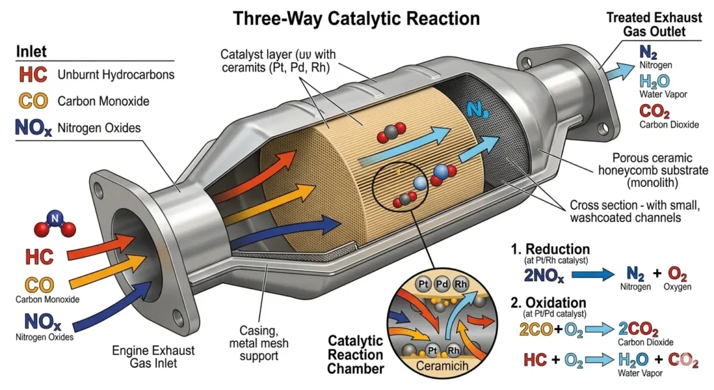
What makes the three-way catalytic converter such an elegant piece of engineering is that it handles all three of these chemically distinct pollutants in a single pass through one device. The reduction and oxidation reactions happen simultaneously across different zones of the same substrate.
How Does a Catalytic Converter Work? The Step-by-Step Chemistry
ThisWhat makes the three-way catalytic converter such an elegant piece of engineering is that it handles all three of these chemically distinct pollutants in a single pass through one device. The reduction and oxidation reactions happen simultaneously across different zones of the same substrate.
Stage 1: The Reduction Catalyst Breaks Down NOx
The first zone the exhaust gas encounters is coated primarily with rhodium and platinum. These metals act as reduction catalysts, meaning they facilitate reactions that remove oxygen atoms from molecules rather than adding them.
When a nitrogen oxide molecule makes contact with the rhodium-coated surface, the catalyst grabs the nitrogen atom and holds it while the oxygen is released as a free oxygen molecule. The nitrogen atoms held on the catalyst surface then bond with other nitrogen atoms in the same position, forming diatomic nitrogen gas (N₂), which is completely harmless and makes up 78% of the air we breathe.
The chemical equations are straightforward:
2NO → N₂ + O₂
2NO₂ → N₂ + 2O₂
Notice that this stage actually produces oxygen as a byproduct. That freed oxygen does not simply escape. It flows downstream into the second zone and becomes a reactant in the oxidation stage, creating a beautifully self-supporting two-stage system within a single converter body.
Stage 2: The Oxidation Catalyst Burns CO and Hydrocarbons
The second zone is coated with platinum and palladium. These act as oxidation catalysts, driving reactions that combine oxygen with carbon monoxide and unburned hydrocarbons. The oxygen produced in Stage 1, combined with any residual oxygen already present in the exhaust stream, is available for these reactions.
Carbon monoxide combines with oxygen over the catalyst surface to produce carbon dioxide:
2CO + O₂ → 2CO₂
Unburned hydrocarbons react with oxygen to produce carbon dioxide and water vapor. Neither carbon dioxide nor water vapor is classified as a toxic pollutant, meaning the converter has successfully completed its function by the time gases exit toward the muffler.
The Oxygen Storage Role of the Substrate
Here is something almost never covered in articles about how a catalytic converter works, and it matters enormously. The ceria-zirconia compounds embedded in the washcoat do not merely provide structural support. They actively store and release oxygen as conditions inside the converter fluctuate.
A real engine does not run at a perfectly constant air-to-fuel ratio. The ratio oscillates slightly rich and slightly lean dozens of times per minute in response to throttle changes, load variations, and sensor feedback. When the exhaust briefly goes lean, meaning there is excess oxygen, the ceria compounds absorb and store that oxygen. When the exhaust briefly goes rich, meaning there is not enough oxygen for complete oxidation reactions, the ceria releases its stored oxygen into the reaction zone.
This oxygen buffering function is what allows the converter to maintain high conversion efficiency even during the natural oscillations of real-world driving. Without it, conversion rates would drop sharply every time the engine moved away from the precise stoichiometric point. Over the life of the converter, this oxygen storage capacity gradually diminishes, which is one reason why converter efficiency declines with age even without any physical damage occurring.
The Air-to-Fuel Ratio and Why It Controls Everything
The efficiency of a catalytic converter is inseparably tied to the air-to-fuel ratio of the engine. The ideal ratio for complete combustion of petrol is 14.7 parts of air to 1 part of fuel by mass. This is known as the stoichiometric point, and it is the precise ratio at which the converter achieves its highest conversion efficiency, typically above 95% for all three pollutant categories.
When the ratio rises above 14.7 (lean mixture), there is excess oxygen in the exhaust. The oxidation reactions work efficiently, but the reduction catalyst struggles because there is too much free oxygen competing with the NOx reduction process. When the ratio falls below 14.7 (rich mixture), there is insufficient oxygen for complete oxidation, and carbon monoxide and hydrocarbon conversion rates fall significantly.
This is why engine tuning, injector health, mass air flow sensor accuracy, and fuel pressure all have a direct downstream impact on how well a catalytic converter works. A perfectly healthy converter fitted to an engine with a fuel delivery problem will perform as poorly as a failing unit.
PCM and Oxygen Sensors: The Catalytic Converter Feedback Loop
The catalytic converter does not operate in isolation. It is one node in a continuous closed-loop control system managed by the vehicle’s Powertrain Control Module (PCM). Understanding this feedback loop is essential to understanding how a catalytic converter works in real operating conditions rather than just in theory.
The upstream oxygen sensor generates a voltage signal that oscillates as the exhaust oxygen content changes. The PCM reads this signal many times per second and adjusts fuel injector pulse width in real time to keep the air-to-fuel ratio as close to stoichiometric as possible. This is the fundamental mechanism that keeps the converter operating in its peak efficiency window.
The downstream oxygen sensor performs a different but equally important role. In a healthy, efficient converter, the chemical reactions inside consume and regulate oxygen so thoroughly that the downstream sensor sees a relatively stable, slow-moving signal compared to the rapidly switching upstream sensor. The contrast between the two signals is itself the diagnostic evidence that the converter is doing its job.
|
Feature |
Upstream O2 Sensor |
Downstream O2 Sensor |
|---|---|---|
|
Position |
Before the converter, closer to engine |
After the converter, closer to muffler |
|
Primary role |
|
|
|
Signal behavior in healthy system |
Rapidly switches between rich and lean readings |
Slow, stable voltage with minimal switching |
|
Signal behavior when converter is failing |
Normal rapid switching |
Begins to mirror upstream sensor, switching rapidly |
|
Consequence of abnormal reading |
PCM adjusts fuel mixture |
PCM logs an efficiency fault code (P0420 or P0430) |
|
|
Directly controls pollutant levels entering the converter |
Confirms whether pollutants have been successfully treated |
When the downstream sensor starts switching as rapidly as the upstream sensor, the PCM recognizes that the converter is no longer buffering and processing exhaust gases properly. The result is a stored fault code and an illuminated check engine light.
Light-Off Temperature: Why Cold Starts Are the Biggest Challenge
One of the most important and most misunderstood aspects of how a catalytic converter works is its relationship with temperature. The precious metal catalysts are not chemically active at low temperatures. The converter requires exhaust gases to heat the substrate to approximately 400 to 600 degrees Fahrenheit before the reduction and oxidation reactions begin occurring at a meaningful rate. This threshold is called the light-off temperature.
During the minutes between engine startup and reaching light-off temperature, the converter passes exhaust gases through almost completely untreated. For drivers who make frequent short trips in cold weather, a significant proportion of every journey may involve the converter operating below its effective threshold. This is not just an emissions concern. It is one of the primary causes of gradual catalyst degradation over time, as partially reacted compounds deposit on the precious metal surfaces and reduce their reactivity.
Once the converter reaches its full operating range of roughly 800 to 1,600 degrees Fahrenheit, conversion efficiency climbs steeply and stays high for the remainder of the drive. Modern engine management systems accelerate warm-up by positioning the converter close to the exhaust manifold, running slightly elevated idle speeds on cold starts to push more hot gas through the system faster, and in some hybrid vehicles, using electric resistance heaters to pre-warm the substrate before the engine even fires.
Interestingly, the opposite extreme is equally damaging. Sustained temperatures above approximately 1,800 degrees Fahrenheit begin to sinter the precious metal particles, causing them to clump together and dramatically reducing the active surface area available for reactions. Engine misfires are the most common cause of this type of overheating, as unburned fuel igniting inside the converter can spike temperatures far beyond the design limits.
OBD2, Readiness Monitors, and P0420: How Cars Self-Test Catalytic Converters
This is a section you will not find in any of the competing articles on how a catalytic converter works, and yet it is precisely the information that most car owners actually need when their check engine light comes on.
Modern vehicles equipped with OBD2 systems run automated self-diagnostic routines called readiness monitors. The catalyst monitor is one of these. During a specific drive cycle that includes a mix of cold start, highway cruising, and deceleration, the PCM evaluates converter efficiency by comparing the switching frequency and amplitude of the upstream and downstream oxygen sensor signals. If the downstream sensor activity exceeds the PCM’s efficiency threshold, a diagnostic trouble code is stored.
Code P0420 indicates catalyst efficiency below threshold on Bank 1. Code P0430 indicates the same condition on Bank 2 of a dual-bank exhaust system. These are the most common converter-related fault codes, and they are frequently misdiagnosed as requiring immediate converter replacement.
In practice, P0420 is just as often triggered by a faulty downstream oxygen sensor, an exhaust leak between the engine and the converter, engine oil burning that has contaminated the catalyst, or a rich-running condition caused by a failing fuel injector or MAF sensor. The code tells you the converter is not meeting the efficiency threshold. It does not tell you why. A proper diagnosis always investigates the upstream causes before condemning the converter itself.
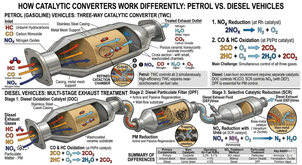
How a Catalytic Converter Works Differently in Diesel vs Petrol Vehicles
Diesel engines present a different set of emissions challenges, and the approach to solving them differs meaningfully from what is used in petrol vehicles.
A conventional three-way catalytic converter requires the engine to operate at or near the stoichiometric point to achieve NOx reduction. Diesel engines run on a lean burn principle, meaning they always run with excess air. This makes NOx reduction through a standard three-way system impractical.
Instead, diesel vehicles use a Diesel Oxidation Catalyst (DOC) to handle carbon monoxide and hydrocarbons, paired with a Diesel Particulate Filter (DPF) to capture soot particles. On larger diesel vehicles and modern Euro 6 compliant passenger cars, a Selective Catalytic Reduction (SCR) system is added. SCR injects a urea-based solution called AdBlue into the exhaust stream upstream of a dedicated catalyst. The urea decomposes into ammonia, which reacts with NOx over the catalyst surface to produce harmless nitrogen gas and water vapor.
This multi-component diesel aftertreatment system achieves results comparable to the three-way converter in petrol vehicles but through an entirely different chemical pathway, reflecting the fundamentally different combustion characteristics of diesel engines.
What Causes a Catalytic Converter to Stop Working Efficiently?
Knowing how a catalytic converter works makes it straightforward to understand why it fails. Every failure mechanism is essentially something that either poisons the catalyst metals, physically destroys the substrate, or prevents the converter from reaching and maintaining operating temperature.
Oil burning is one of the most damaging failure causes. When engine oil enters the combustion chamber through worn valve seals or piston rings, it produces phosphorus compounds in the exhaust. Phosphorus is a potent catalyst poison that coats the precious metal surfaces and permanently deactivates them. Coolant entering the exhaust through a leaking head gasket deposits silicone compounds with the same poisoning effect.
Lead, while no longer present in petrol sold in most markets, remains a concern in some regions and destroys catalyst activity almost immediately by physically coating and blocking the reactive surfaces.
Engine misfires send pulses of unburned fuel directly into the hot converter, where it ignites and generates heat spikes well above the substrate’s design tolerance. Even a few minutes of severe misfiring can melt the ceramic honeycomb, blocking exhaust flow and creating catastrophic backpressure.
Gradual thermal cycling over many years and miles causes a slow sintering of the precious metal particles and a reduction in the oxygen storage capacity of the ceria compounds in the washcoat. This type of age-related degradation is inevitable and explains why converters that show no dramatic failure event still decline in efficiency over time.
James Mitchell
Senior Automotive Writer
12+ years writing clear, practical guides on vehicle maintenance and emissions systems.
